or click on the tabs for navigation.
| [ File ] | [ Place ] | [ Grab ] | [ Edit ] | [ Delete ] | [ Un-Do ] | [ Setup ] | [ Block ] | [ Nets ] | [ Zoom ] | [ Help ] | |
|
|||||||||||
| Previous Page |
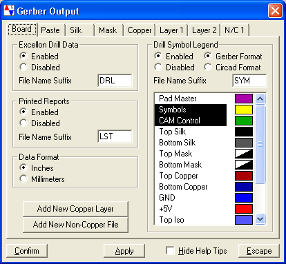
File Menu: Gerber Out | Next Page |
| Hover over the image for pop-up help, or click on the tabs for navigation. |
|